

How to Read a Pipe Loss Coefficient Chart
Experiment #three: Energy Loss in Pipe Fittings
ane. Introduction
Two types of energy loss predominate in fluid flow through a pipe network; major losses, and pocket-size losses. Major losses are associated with frictional energy loss that is acquired by the viscid effects of the medium and roughness of the piping wall. Minor losses, on the other hand, are due to pipe fittings, changes in the flow management, and changes in the period surface area. Due to the complexity of the piping system and the number of fittings that are used, the head loss coefficient (One thousand) is empirically derived every bit a quick means of calculating the pocket-size head losses.
2. Applied Application
The term "minor losses", used in many textbooks for head loss across fittings, can be misleading since these losses can exist a large fraction of the total loss in a pipe system. In fact, in a pipe system with many fittings and valves, the minor losses can be greater than the major (friction) losses. Thus, an accurate K value for all fittings and valves in a pipe system is necessary to predict the bodily head loss across the pipe organisation. K values aid engineers in totaling all of the minor losses by multiplying the sum of the K values past the velocity caput to chop-chop determine the full caput loss due to all fittings. Knowing the G value for each plumbing equipment enables engineers to employ the proper fitting when designing an efficient pipage arrangement that tin can minimize the head loss and maximize the flow rate.
3. Objective
The objective of this experiment is to determine the loss coefficient (Thousand) for a range of pipe fittings, including several bends, a wrinkle, an enlargement, and a gate valve.
4. Method
The head loss coefficients are determined by measuring the pressure head differences beyond a number of fittings that are connected in series, over a range of steady flows, and applying the energy equation between the sections earlier and afterward each fitting.
5. Equipment
The following equipment is required to perform the energy loss in pipe fittings experiment:
- F1-x hydraulics demote,
- F1-22 Free energy losses in bends apparatus,
- Stopwatch for timing the flow measurement,
- Clamps for pressure tapping connection tubes,
- Spirit level, and
- Thermometer.
half-dozen. Equipment Description
The energy loss in fittings apparatus consists of a series of fittings, a period control valve, twelve manometers, a differential pressure guess, and an air-drain valve (Figure three.1).
The fittings listed below, connected in a series configuration, will be examined for their caput loss coefficient (K):
- long curve,
- area enlargement,
- expanse contraction,
- elbow,
- brusque bend,
- gate valve, and
- mitre.
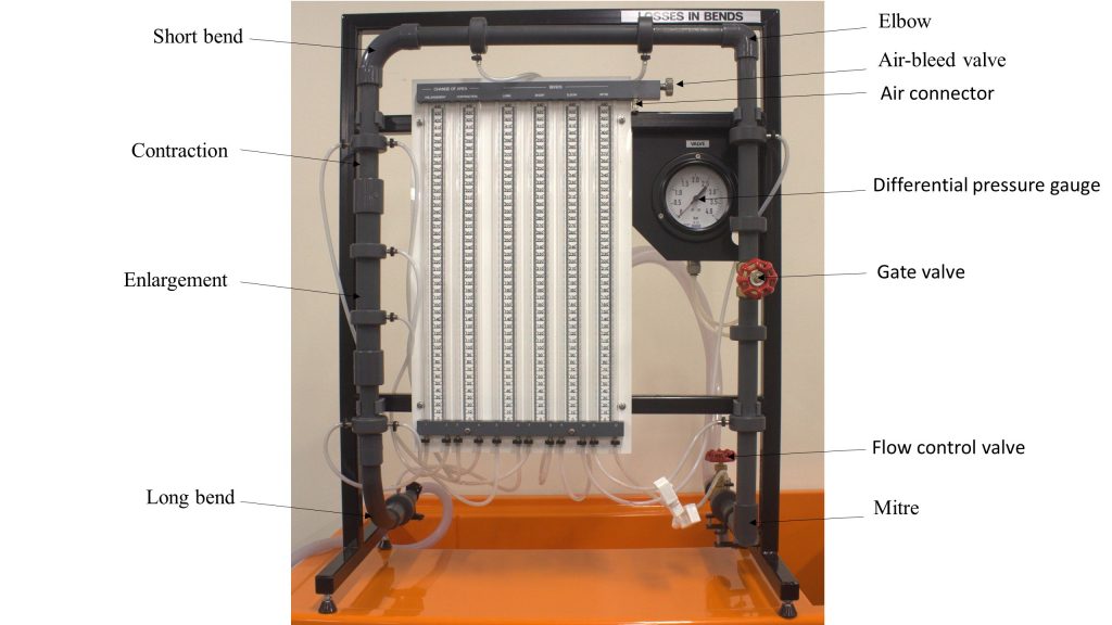
The manometers are tapped into the pipe system (one before and one after each plumbing equipment, except for the gate valve) to measure the pressure caput difference acquired by each fitting. The pressure difference for the valve is directly measured by the differential pressure gauge. The air-bleed valve facilitates purging the system and adjusting the water level in the manometers to a convenient level, past allowing air to enter them. 2 clamps, which close off the tappings to the mitre, are introduced while experiments are beingness performed on the gate valve. The menstruation rate is controlled past the menstruation control valve [3].
The internal diameter of the pipe and all fittings, except for the enlargement and contraction, is 0.0183 one thousand. The internal bore of the pipage at the enlargement's outlet and the contraction's inlet is 0.0240 m.
7. Theory
Bernoulli'south equation tin can exist used to evaluate the energy loss in a pipe organization:
![[\frac{P}{\gamma}+\frac{v^2}{2g}+z]_{in}=[\frac{P}{\gamma}+\frac{v^2}{2g}+z]_{out}+h_L\qquad (1)](https://uta.pressbooks.pub/app/uploads/quicklatex/quicklatex.com-12b9019e10aaa7917e4a961e3d4ea76a_l3.png "Rendered by QuickLaTeX.com")
In this equation  ,
,  , and z are pressure head, velocity head, and potential caput, respectively. The total head loss, h50, includes both major and minor losses.
If the diameter through the pipe fitting is kept constant, so  . Therefore, if the change in pinnacle head is neglected, the manometric caput difference is the static caput difference that is equal to the pocket-sized loss
  through the plumbing equipment.
![[\frac{P}{\gamma}]_{in}-[\frac{P}{\gamma}]_{out}=H_1-H_2={\Delta{h}}\qquad (2)](https://uta.pressbooks.pub/app/uploads/quicklatex/quicklatex.com-ae49fd18a1bb03cee79bd0b04d3c3364_l3.png "Rendered by QuickLaTeX.com")
in which  and
and  are manometer readings earlier and subsequently the fitting.
The energy loss that occurs in a piping fitting tin can likewise be expressed every bit a fraction (K ) of the velocity head through the plumbing fixtures:

where:
K: loss coefficient, and
v: hateful flow velocity into the plumbing fixtures.
Because of the complication of the flow in many fittings, G is usually determined past experiment [3]. The caput loss coefficient (K) is calculated equally the ratio of the manometric caput difference between the input and output of the fitting to the velocity head.

Due to the change in the pipe cross-sectional surface area in enlargement and wrinkle fittings, the velocity divergence cannot be neglected. Thus:
![(H_1-H_2)+([\frac{v^2}{2g}]_{in}-[\frac{v^2}{2g}]_{out})={\Delta{h}}\qquad (5)](https://uta.pressbooks.pub/app/uploads/quicklatex/quicklatex.com-71debfacef2c2944d2be26e032ce0586_l3.png "Rendered by QuickLaTeX.com")
Therefore, these types of fittings experience an additional change in static pressure, i.e.:
![([\frac{v^2}{2g}]_{in}-[\frac{v^2}{2g}]_{out})](https://uta.pressbooks.pub/app/uploads/quicklatex/quicklatex.com-704824acde5a3c0e388f340a8940bef4_l3.png "Rendered by QuickLaTeX.com") .
.
This value volition be negative for the wrinkle since  and information technology will be positive for enlargement because
  . From Equation (5), note that volition be negative for the enlargement.
The pressure departure ( ) between earlier and subsequently the gate valve is measured directly using the pressure gauge. This tin and so exist converted to an equivalent caput loss by using the conversion ratio:
1 bar= ten.2 m water
The loss coefficient for the gate valve may and so exist calculated by using Equation (four).
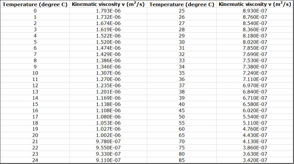
To identify the flow regime through the plumbing equipment, the Reynolds number is calculated equally:

where v is the cross-exclusive mean velocity, D is the pipage diameter and  is the fluid kinematic viscosity (Figure iii.ii).
8. Experimental Process
It is not possible to measure head due to all of the fittings simultaneously; therefore, it is necessary to run two separate experiments.
Function A:
In this function, head losses acquired by fittings, except for the gate valve, will be measured; therefore, this valve should exist kept fully open throughout Part A. The following steps should be followed for this part:
- Ready the appliance on the hydraulics bench and ensure that its base is horizontal.
- Connect the appliance inlet to the bench flow supply, run the outlet extension tube to the volumetric tank, and secure it in place.
- Open up the demote valve, the gate valve, and the menstruation control valve, and kickoff the pump to make full the pipe system and manometers with water. Ensure that the air-bleed valve is closed.
- To purge air from the pipe arrangement and manometers, connect a diameter tubing from the air valve to the volumetric tank, remove the cap from the air valve, and open up the air-drain spiral to let menses through the manometers. Tighten the air-bleed screw when no air bubbling are observed in the manometers.
- Set the flow rate at approximately 17 liters/minute. This tin be accomplished by several trials of timed volumetric flow measurements. For flow measurement, close the brawl valve, and use a stopwatch to measure out the time that it takes to accrue a known volume of fluid in the tank, which is read from the hydraulics bench sight drinking glass. Collect h2o for at least one minute to minimize errors in the menstruum measurement.
- Open the air-bleed screw slightly to allow air to enter the summit of the manometers; re-tighten the screw when the manometer levels reach a user-friendly height. All of the manometer levels should be on scale at the maximum menstruation rate. These levels can be adapted further past using the air-bleed screw and the hand pump. The air-bleed spiral controls the air flow through the air valve, so when using the hand pump, the drain screw must be open. To retain the hand pump pressure in the system, the screw must be airtight later pumping [iii].
- Take superlative readings from all manometers after the levels are steady.
- Repeat this procedure to requite a total of at to the lowest degree v sets of measurements over a flow range of eight – 17 liters per minute.
- Measure the outflow water temperature at the lowest flow rate. This, together with Effigy three.two, is used to determine the Reynolds number.
Part B:
In this experiment, the caput loss across the gate valve will be measured by taking the following steps:
- Clamp off the connecting tubes to the mitre bend pressure tappings to forestall air beingness drawn into the arrangement.
- Open up the bench valve and set up the menstruation at the maximum menstruum in Part A (i.e., 17 liter/min); fully open the gate valve and flow command valve.
- Arrange the gate valve until 0.three bar of caput difference is achieved.
- Determine the volumetric flow rate.
- Echo the experiment for 0.half dozen and 0.9 confined of pressure difference.
9. Results and Calculations
Please visit this link for accessing excel workbook for this experiment.
9.1. Results
Record all of the manometer and pressure level judge readings, as well as the volumetric measurements, in the Raw Information Tables.
Raw Information Tables
Part A – Head Loss Across Pipe Fittings
| Exam No. 1: Volume Collected (liters): | Time (s): | |
| Fitting | hone (chiliad) | h2(m) |
| Enlargement | ||
| Contraction | ||
| Long Bend | ||
| Brusk Curve | ||
| Elbow | ||
| Mitre | ||
| Test No. 2: Volume Nerveless (liters): | Time (s): | |
| Enlargement | ||
| Wrinkle | ||
| Long Bend | ||
| Curt Curve | ||
| Elbow | ||
| Mitre | ||
| Test No. 3: Volume Collected (liters): | Time (south): | |
| Enlargement | ||
| Contraction | ||
| Long Bend | ||
| Short Bend | ||
| Elbow | ||
| Mitre | ||
| Test No. iv: Volume Collected (liters): | Time (due south): | |
| Enlargement | ||
| Contraction | ||
| Long Bend | ||
| Curt Bend | ||
| Elbow | ||
| Mitre | ||
| Exam No. 5: Volume Collected (liters): | Time (s): | |
| Enlargement | ||
| Contraction | ||
| Long Bend | ||
| Short Bend | ||
| Elbow | ||
| Mitre | ||
Role B – Head Loss Across Gate Valve
| Head Loss (bar) | Book (liters) | Fourth dimension (s) |
| 0.3 | ||
| 0.half-dozen | ||
| 0.9 | ||
| Water Temperature: | ||
9.2. Calculations
Calculate the values of the discharge, flow velocity, velocity head, and Reynolds number for each experiment, too equally the Thousand values for each fitting and the gate valve. Record your calculations in the post-obit sample Upshot Tables.
Consequence Table
Part A – Caput Loss Across Pipe Fittings
| Test No: | Menses Charge per unit Q (mthree/south): | Velocity v (m/s): | |||||
| Fitting | hone (m) | htwo(m) | =h1– h2 (m) | Corrected (m) | v2/2g (m) | K | Reynolds Number |
| Enlargement | |||||||
| Contraction | |||||||
| Long Bend | |||||||
| Short Bend | |||||||
| Elbow | |||||||
| Mitre | |||||||
Part B – Head Loss Across Piping Fittings
| Head Loss | Volume (m3) | Time (s) | Catamenia Rate Q (m3/southward) | Velocity (m/s) | five2/2g (m) | K | Reynolds Number | |
| (bar) | (m) | |||||||
| 0.3 | ||||||||
| 0.6 | ||||||||
| 0.ix | ||||||||
10. Report
Employ the template provided to ready your lab report for this experiment. Your study should include the following:
How to Read a Pipe Loss Coefficient Chart
Source: https://uta.pressbooks.pub/appliedfluidmechanics/chapter/experiment-3/
0 Response to "How to Read a Pipe Loss Coefficient Chart"
Post a Comment